Product line 01
High-Frequency PCB
High-frequency PCB fabrication on Rogers, Taconic and PTFE laminates. 2–32 layers, impedance held to ±5% and verified by TDR. DFM review within 24 hours.
2 – 32Layers
2.2 – 10.2Dk range
±5%Impedance
8 – 12 dLead time
Catalogue
Boards we build on this line.
Representative items from this line’s catalogue. Open a board for its build parameters — every card leads to its own detail page.
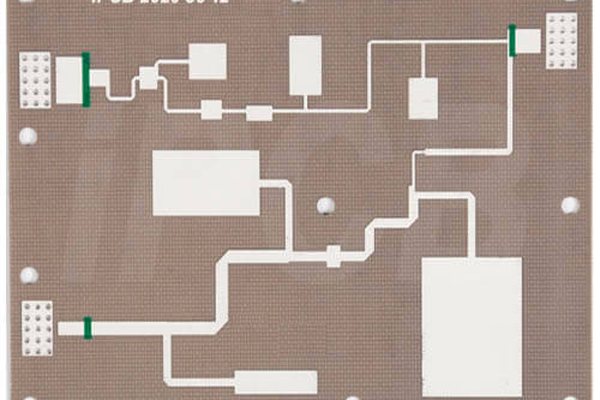
Rogers RF Front-End Board
2–4 · Rogers RO4350B · 3.48 ±0.05
View this board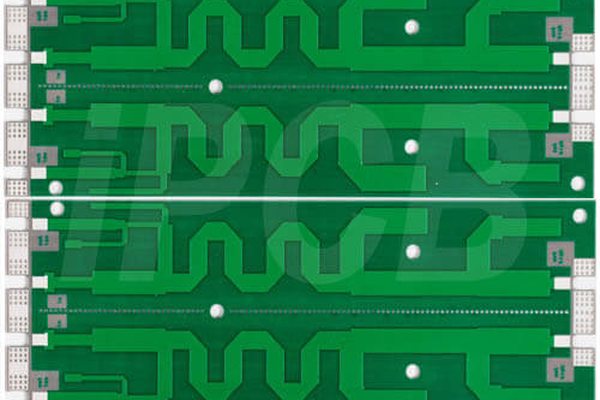
PTFE Antenna Feed Network
2L · PTFE (Dk 2.2) · ±0.1 mm
View this board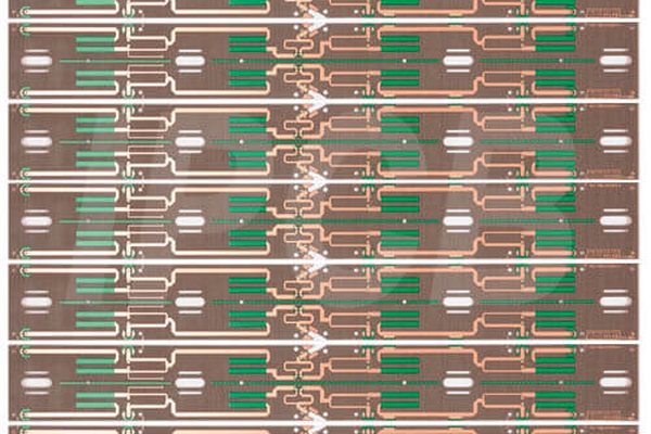
Hydrocarbon 5G Array Panel
4L · Hydrocarbon + FR-4 cap · 3.0–3.6
View this board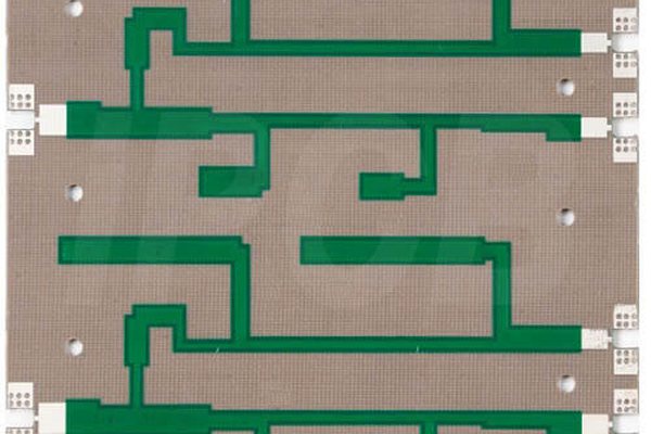
Mixed-Dielectric PA Board
4–6 · PTFE core + FR-4 · ±5% (TDR)
View this board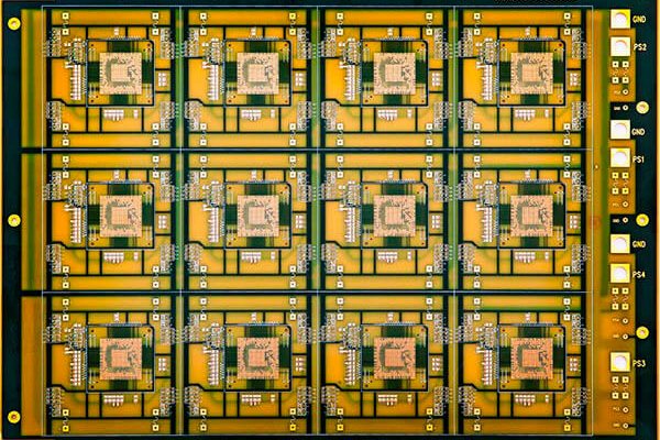
Ceramic Microstrip Array
2L · Ceramic-filled PTFE · ±15 µm
View this board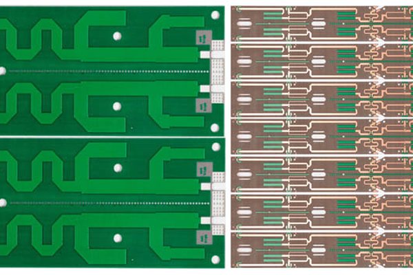
Dual-Band Repeater Board
4L · Rogers + FR-4 hybrid · ±5% (TDR)
View this boardTechnical specifications
High-Frequency PCB
| Layers | 2 – 16 |
| Board thickness | 0.8 – 3.2 mm |
| Base material | Rogers RO4350B, RO4003C |
| Dielectric constant (Dk) | 3.0 – 4.5 |
| Dissipation factor (Df) | ≤ 0.004 |
| Where it is used | 5G base stations · Radar · Microwave |
Other product families
No obligation
Send the file. Get a real answer.
Upload a Gerber and we will come back within 24 hours with the DFM issues, a price and a lead time. If your design is not a fit for our process, we will say so.